My niece has a cute little toy with some switches and LEDs in a nice wooden enclosure that I like to fiddle with. The toy is meant for young children so the interaction is limited. I thought it would be fun to make something similar but with a sprinkle of digital logic. A binary adder sounded like something I could accomplish using a bit of spare time over the summer.
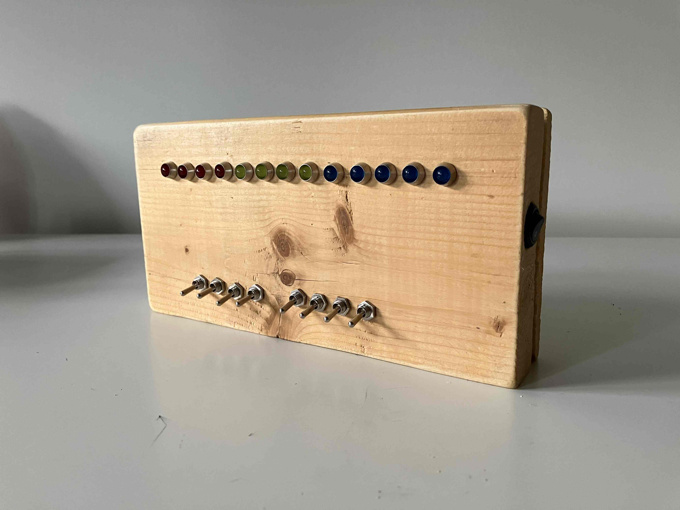
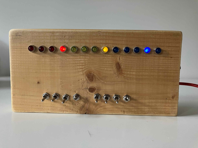
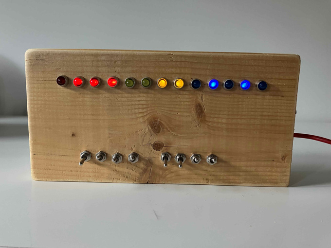
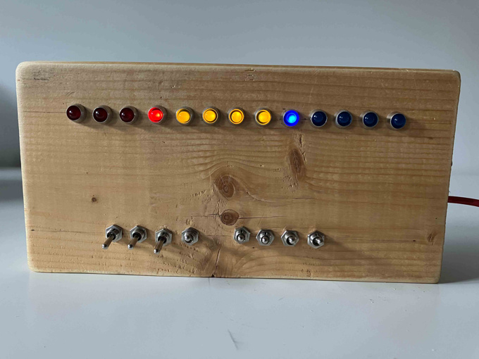
I made it with a hollowed out piece of scrap wood. It has a line of thirteen LEDs controlled by eight switches. From left to right, the first four LEDs are red and represent the first number to be added. The next four LEDs are yellow and represent the second number to be added. The last five LEDs are blue and represent the result. If you're familiar with binary numbers, the next couple of examples should showcase the working adder. If you're not familiar with binary numbers, there's an interactive example coming up that might help build some intuition.
The box below emulates the behavior of the adder. Click on the red and yellow circles to see the result in the blue circles. If you're not familiar with binary, it's a different numbering system where, instead of having ten possible symbols per digit (0 through 9), there are only two: 0 and 1. Digital electronics are made using transistors which can be thought of as on-off switches that are controlled with electricity. Since we only have on-off states to work with, it makes sense to work with numbers in this binary system.
The adding is done with a single 74LS83 chip. This is part of a family of chips that were popular in the 60s to the 80s for building computers and other electronics. Today, they are still useful for learning digital logic. The data sheet provides a pin diagram showing how to wire up the chip:
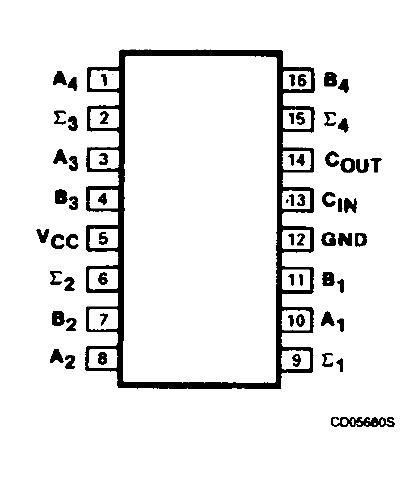
VCC and GND are for powering the chip. The A and B pins are the inputs for the numbers to be added where A1 and B1 are the least significant bits, and A4 and B4 are the most significant. If you're not familiar with the term "least significant", it just means the rightmost digit (it contributes the least to the overall number), so, using a decimal number like 5129, the rightmost number "9" is the least significant. It's the same for a binary number like 1000, where it would be broken down as A1=0 (least significant), A2=0, A3=0, A4=1 (most significant). The Σ pins are the outputs for the resulting number from adding A and B. The output is a bit more complicated since we actually use COUT (stands for carry out) as the most significant bit, so we have five bits to represent the result. If you look at the previous example of adding 15 + 1 you'll see that adding the two four-bit numbers needs a fifth bit to represent the result. This is like how adding two single digit numbers like 9 + 1 needs two digits to represent the result of 10. The CIN (stands for carry in) pin is used for connecting multiple 74LS83 chips together by connecting one chips COUT pin to anothers CIN pin for adding larger numbers. You can chain multiple together this way.
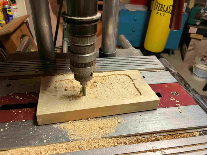
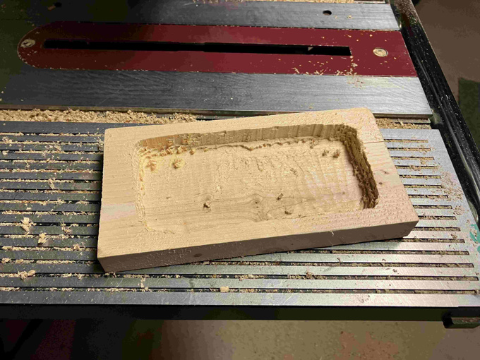
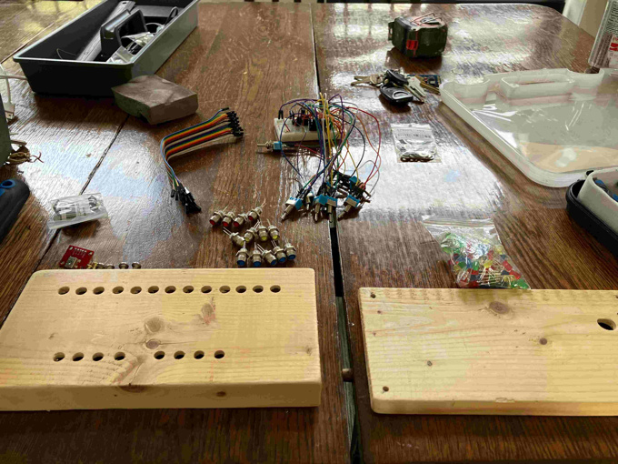
For the enclosure I took a piece of 2x6 from a scrap pile in the yard, cut about a centimeter off the back, and hollowed out the larger remaining piece. Layer by layer, I painstakingly used a drillpress to hollow it out, thinking the whole time that there has to be a faster way of doing it. Nothing more efficient came to mind so I pressed on, and a couple of hours later I had a hollowed out piece of wood:
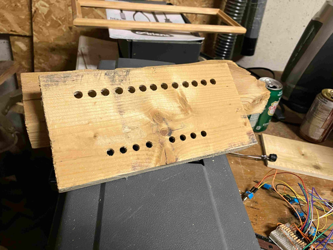
Then holes were drilled for the LEDs and switches on the front. A hole was drilled into the side for a power switch and another hole was drilled into the back for the usb power connector.
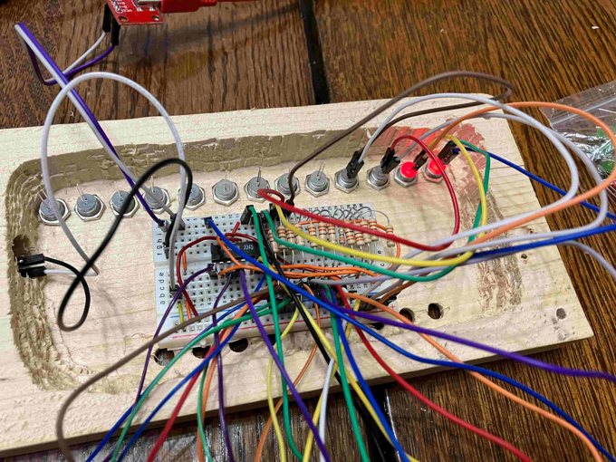
After some sanding and a thin coat of finish, it's ready to be assembled. I didn't go through the process of making a proper circuit board and just used a small breadboard to put inside the enclosure.
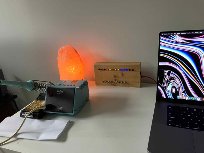
Overall I'm happy with how it looks and functions but there's a couple things I'm not satisfied with. The biggest thing is I ordered the wrong switches. I should have ordered simple on-off switches with two pins. Instead, I ordered what are called single pole double throw (SPDT) switches which have three positions instead of just on and off. I decided to go ahead and finish the project with these switches and have come to regret it as the middle positions put it in an invalid state. I also found shoving the breadboard inside pretty inelegant and could have at least made a prototype circuit.